What is All Pass Filter (APF)
This page covers All Pass Filter basics. It compares first order vs second order All Pass filter and mention difference between first order all pass filter and second order all pass filter.
Usually we have seen that amplitude response is very important in filtering operation. Based on these various types of filters are named such as LPF, HPF and so on. The type of filter which does not change amplitude of the input signal and introduces phase shift is referred as All pass filter. It is also known by name 'APF' filter.
The function of All Pass filter is to introduce phase shift or phase delay
to the response of the circuit.
➨Amplitude of the filter is unity for all the frequencies.
➨Phase response is changing from 0 degree to 360 degree.
All Pass Filter Applications:
➨It is used to provide phase equalization:
➨It is used in single side band suppressed carrier i.e. SSB-SC modulation based
circuit designs.
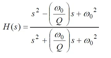
The Transfer function of All Pass Filter can be expressed as mentioned above.
It can be synthesized to the following equation:
HAP = HLP - HBP + HHP = 1 - 2* HBP
Difference between First order All Pass Filter vs second order All Pass Filter
The All-Pass Filters are designed using Operational Amplifier and discrete resistors and capacitors. The first order and second order circuit of All-Pass Filter have been mentioned below.
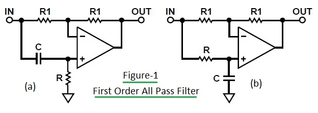
The figure-1 depicts First Order All Pass Filter circuit. The fig-1 (a) depicts high pass equivalent and fig-1 (b) depicts low pass equivalent of the all pass filter.
The circuit in fig-1(a) has phase shift variation from -180 degree (at 0 Hz frequency) to 0 degree (at higher frequency). At w = 1/RC, the value of phase shift is -90 degree.
Variable resistor can be used in the circuit which helps in adjustment of delay at particular frequency.
The circuit in fig-1(b) has phase shift variation from 0 degree (at DC frequency) to -180 degree (at higher frequency).

Above equations are used as design equations for first order all pass filter(high pass equivalent as shown in fig-1 (a)).

The figure-2 depicts Second Order All Pass Filter circuit. The design equations of the second order APF are mentioned below.

In order to design the filter of the above second order All Pass type,
Choose C and determine other components as per following equations.
Please note that these filters have not been realized by anyone at the RF Wireless World.
➨ k = 2*π*Fo*C
➨R2 = (2*Q)/k
➨R1 = 1/(2*k*Q)
➨R3 = R1
➨R4 = Q2*R3
References
https://forum.allaboutcircuits.com/threads/2nd-order-all-pass-filter-design.43869/
Filter RELATED LINKS
LPF vs HPF vs BPF vs BSF
analog vs Digital Filter
FIR vs IIR filter
Low Pass FIR filter MATLAB implementation
Analog LPF vs HPF MATLAB source code
What is Difference between
FIR filter Vs. IIR filter
difference between FDM and OFDM
Difference between SC-FDMA and OFDM
Difference between SISO and MIMO
Difference between TDD and FDD
Difference between 802.11 standards viz.11-a,11-b,11-g and 11-n
OFDM vs OFDMA
CDMA vs GSM
Bluetooth vs zigbee