


Resources
Wiki
oldcomputer.info
zimmers.net
Documents
Internals
Motherboard


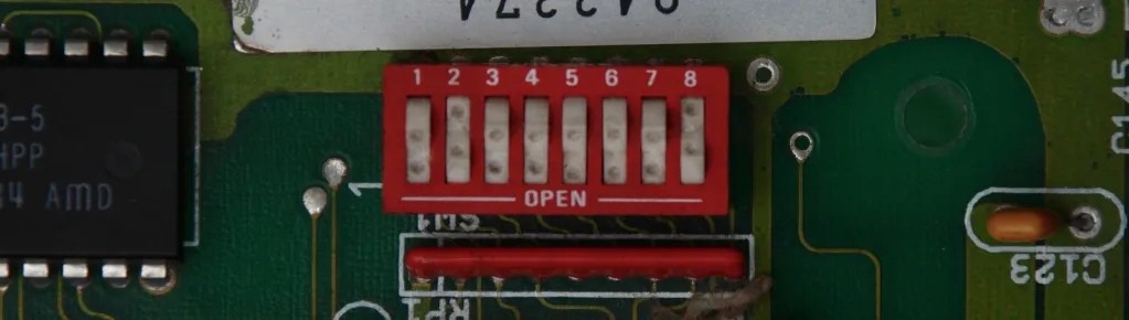
Jumper settings on the “Commodore PC Combined Motherboard”. If you wonder why this motherboard is called “combined”, please take a look at what Commodore PC 10 motherboard looks like.

RAM Extension Module


Power Supply


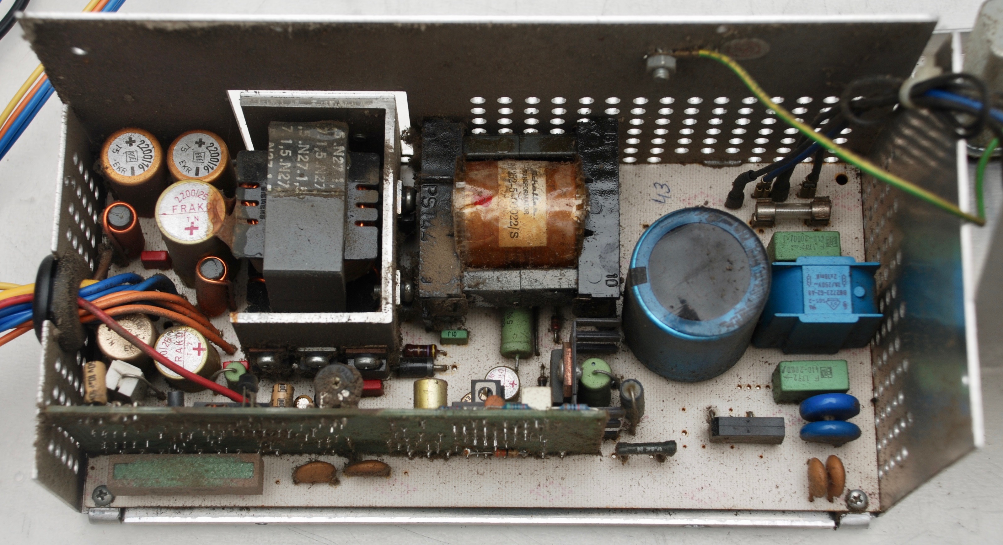
If voltages provided by the power supply are low and the “power ready” output is not active, please check the potentiometer located on the small vertical board first. It is prone to getting dirty inside and stops conducting. It may be enough to turn in back and forth to clean it up and it may start working again. Calibrate the 5V output with a multimeter after that. Recapping is also a very good idea.
The power connector has the following pinouts:
1   - Brown:  Power Good (+5V when power is ready)
2   - Red:    -12V
3   - Orange: +12V
4,5 - Blue:   Ground
6   - Yellow: +5V
Graphics Card
ATI Graphics Solution CW16800-A Rev.3 part number 168228. The configuration using on-board switches is on one of the pictures.


Floppy Disk Drives
360KB ALPS DFC222A05A. For more detailed pictures of the disassembled drive visit PC 20-II page.


Both drives share the same cable without a “twist”, booting drive is set as DS0 and secondary drive as DS1. Other jumper configuration is on the pictures below.


Hard Disk Drive
My PC10-II did not come with a HDD, but I successfully connected Western Digital WX3 Winchester Controller and ST-251-1 MFM drive. Prior to being recognized by the PC10-II, the drive needs low level formatting – all instructions are in the controller user manual: Western_Digital_WX3-WX3R. I did not manage to get more than 20MB from this 40MB drive, but I don’t know if it is a matter of low level format parameters or PC configuration.


Reassembly


Some Dirt
1 Response
[…] switches have exactly the same meaning as in Commodore PC 10-II. This motherboard works only with pure XT keyboard. PC-10-III keyboard, although it may work with […]