ZX81/TIMEX-SINCLAIR 1000 Custom Mechanical Keyboard Prototype - Part 2


This is the second part of a two part post in which I share every step of designing and building a prototype mechanical keyboard for my TS-1000, or with some adaptation, could be applied to other models of retro computers. Part 1 covers the design and manufacture of the acrylic key switch mounting plate up to the test fit of the key switches.
This part covers the the wiring of the key switch matrix, connecting the keyboard to the TS-1000, designing the key cap label SVG (Scalable Vector Graphics) template in Inkscape, printing the waterslide decals, and how to apply the decals to the key caps so they don't peel off after a day and a half. 🤬
Key Switch Matrix Wiring Guide
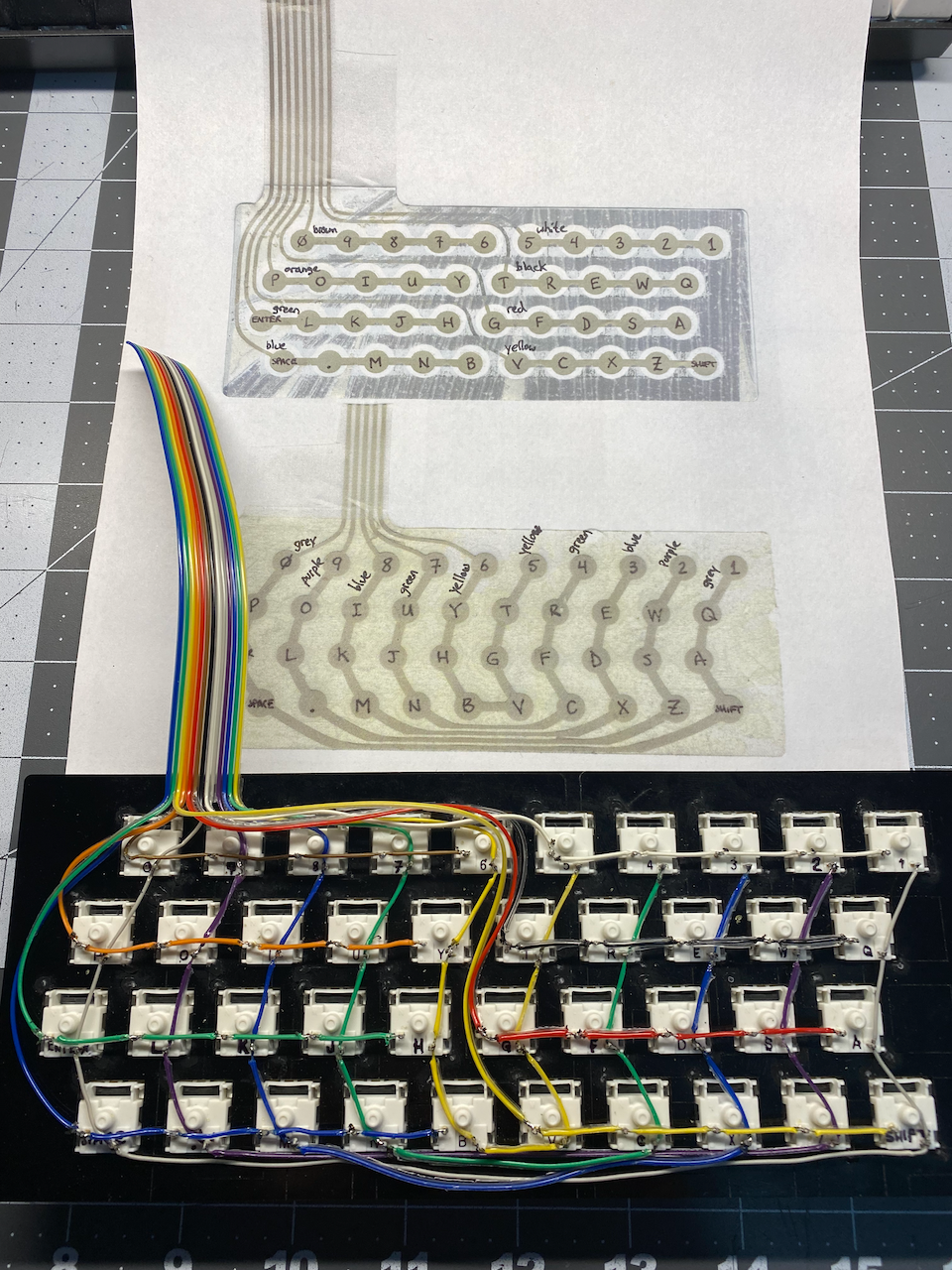
The ZX81/TS-1000 keyboard matrix is simplicity itself in its design. The keyboard has forty key switches "physically" arranged in a matrix of four rows and ten columns, but "electrically" the matrix consists of eight rows of five key switches each, and five doubled/paired columns of four key switches each making groups of eight. Representations of the keyboard matrix can be found in various sources online, but I happened to have a damaged keyboard membrane that was old, brittle, and kinked that I could dissect and make into a wiring legend.
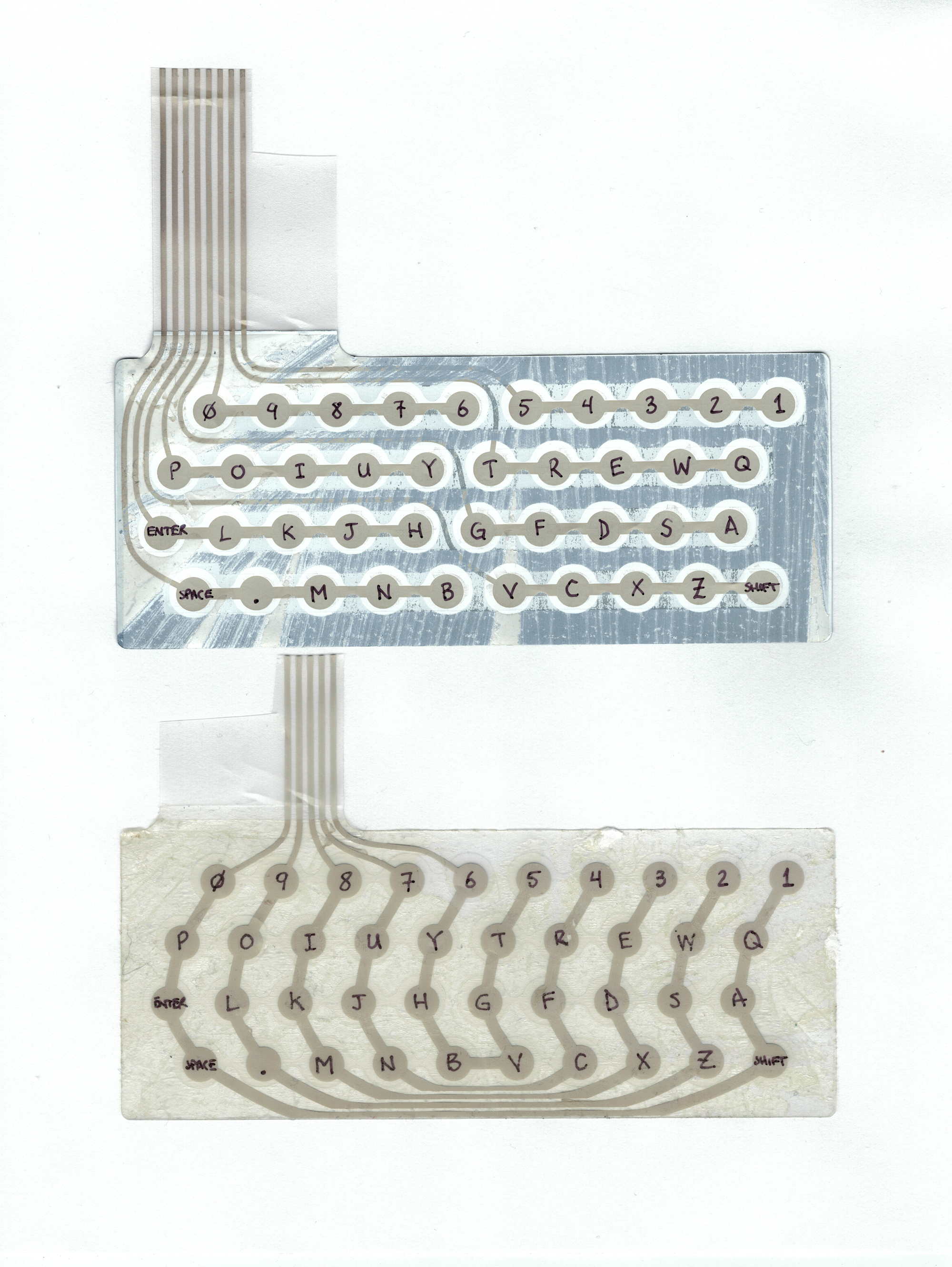
I figured that while soldering a whole bunch of wires on the back of a matrix of forty switches (80 soldering points), it would be helpful to have the bottoms of the key switches labeled and also have a wiring pattern/guide to follow. For the wiring guide, I peeled the keyboard membrane apart and stuck the two halves onto a blank sheet of "U.S. Letter Size" paper with double sided tape, and then used a fine point permanent marker to label the key membrane contacts.
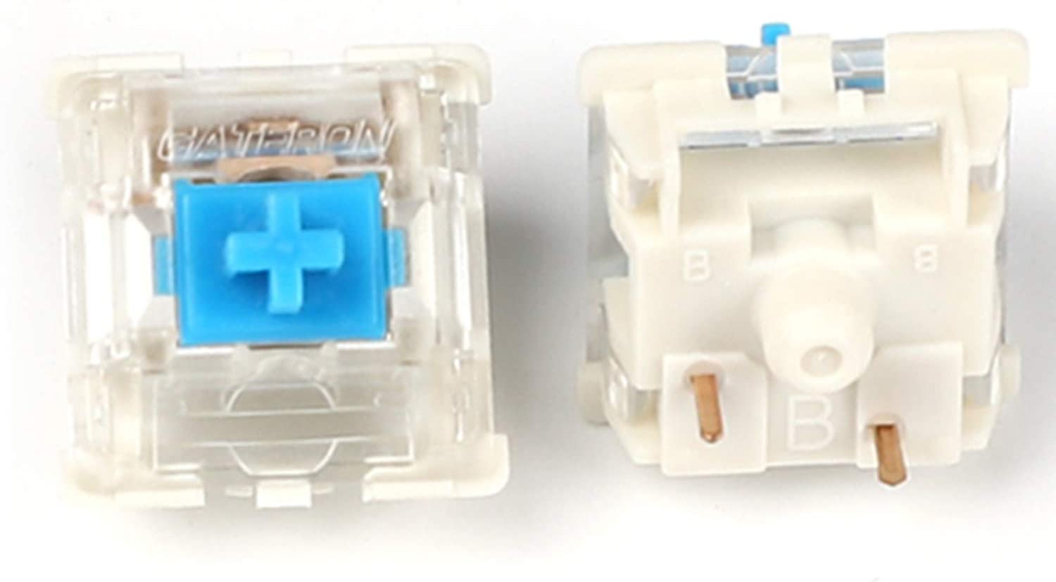
I purchased a bag of 68 Gateron "Blue" key switches on Amazon. Getting key switches direct from Gateron appears to be an issue, as they have been "Sold Out" the last few times I have checked. But since I started building my prototype all the way up to the time of this writing, the ones I purchased on Amazon are still available.
I am unsure about whether or not there is normally a system to the molded labels on the bottom side of the Gateron key switches, but my bag of switches seemed to have duplicates of certain letters or numbers, while some letters were not present at all. Nonetheless, I took my trusty fine point permanent marker and labeled all of the key switches to help me while soldering the wires onto the switch contacts. With all of the key switches labeled, I glued them into the acrylic base plate by applying two small dots of super glue on opposite corners of each key switch.
Soldering The Key Switch Matrix
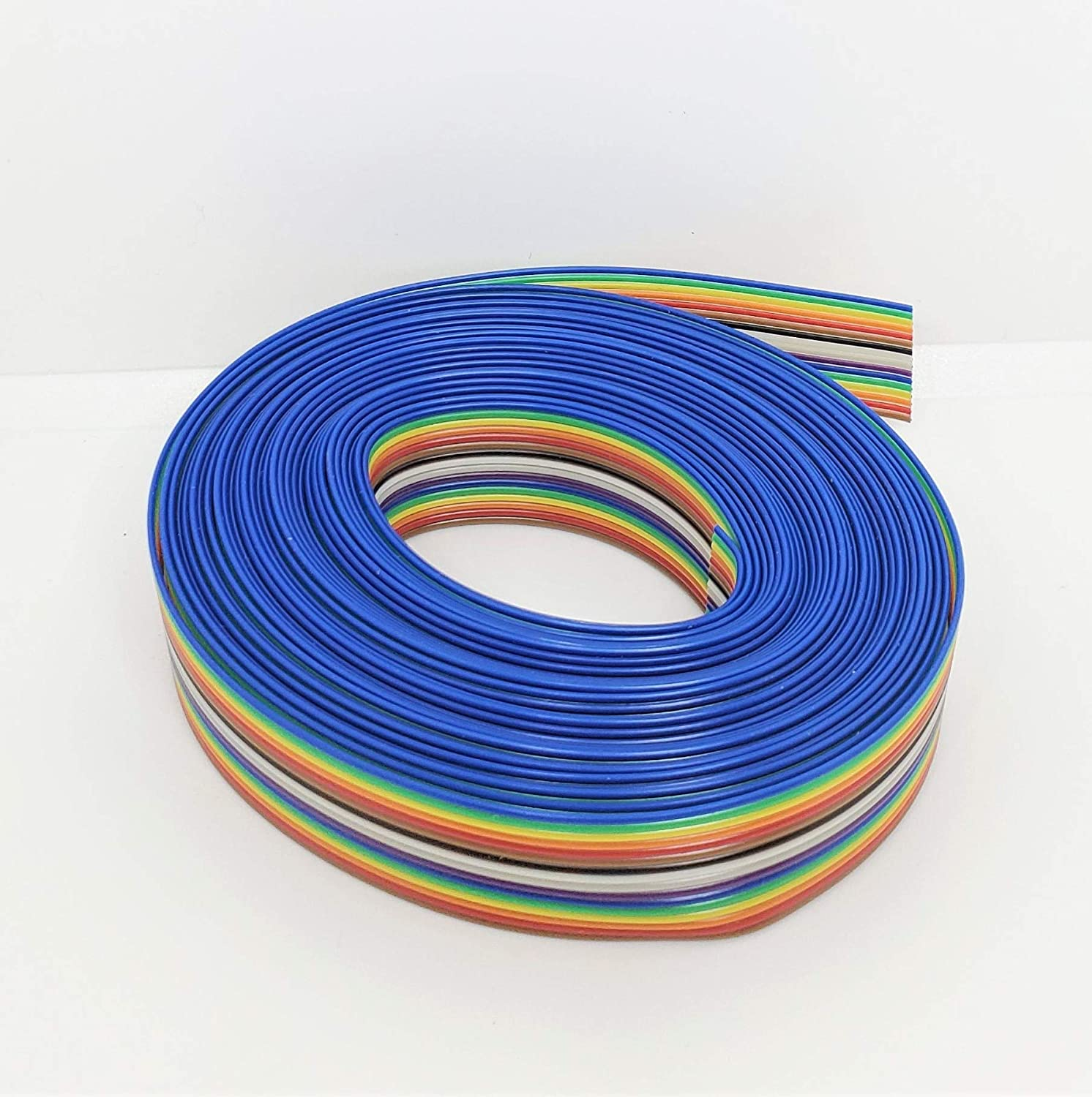
There is something very cool about rainbow colored ribbon cable! It is not only aesthetically pleasing, but color coding wires makes troubleshooting electrical systems much easier and can sometimes even eliminate the need for numbering/labeling wires. I knew before I started this project, "THERE WILL BE RAINBOW COLORED RIBBON CABLE!!!" I found a reasonably priced ribbon cable with good reviews and the minimum count I would need on Amazon.
With the key switches all labeled and glued into the base plate, I cut a length of the ribbon cable so as not to restrict movement between the prototype keyboard and the TS-1000 PCB, and also to make sure that each wire would be able to reach the longest path to the furthest key in either a column or row connection.
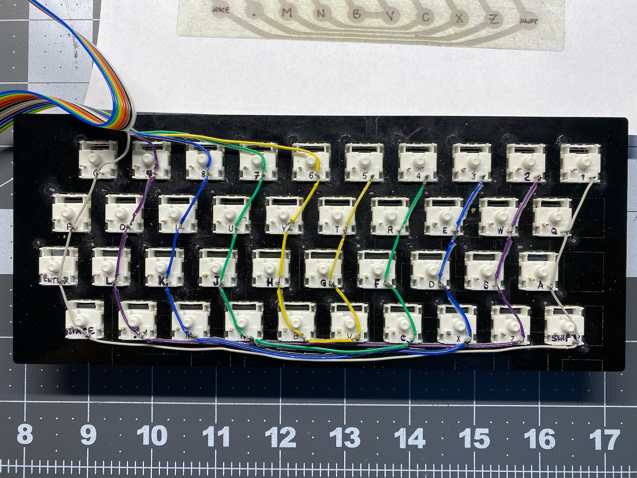
Rather than cutting individual short lengths of wire, I decided to just use the soldering iron to melt the insulation of the wire at the switch contact, thereby keeping one continuous length of wire in each column & row.
VERY IMPORTANT NOTE: When melting plastic/PVC (whatever the ribbon cable insulation is made of) there will be fumes, and those fumes are certain to be toxic! MAKE SURE TO HAVE GOOD VENTILATION AND AVOID INHALING THE FUMES!
Testing The Connections
I first soldered all of the column connections on the right hand side contacts. When the columns were all soldered, I tested each switch & solder connection by connecting one lead of a multimeter to the left contact of a switch, and the other lead on any point of the common column wire. With the multimeter set to resistance, and the "Beep" enabled (if your meter has one), press that key switch, listen for the beep and make sure the resistance isn't too far above the resistance of your leads (usually less than 1 Ohm). Repeat for each key.
Once all of the columns were soldered and tested, I repeated the process with the row connections. There were a few connections that did not bond well and had higher resistances than I wanted, but fixing that simply meant reheating with the soldering iron and moving the connection back and forth a little for a better connection.
Dupont Connectors & Pin Headers
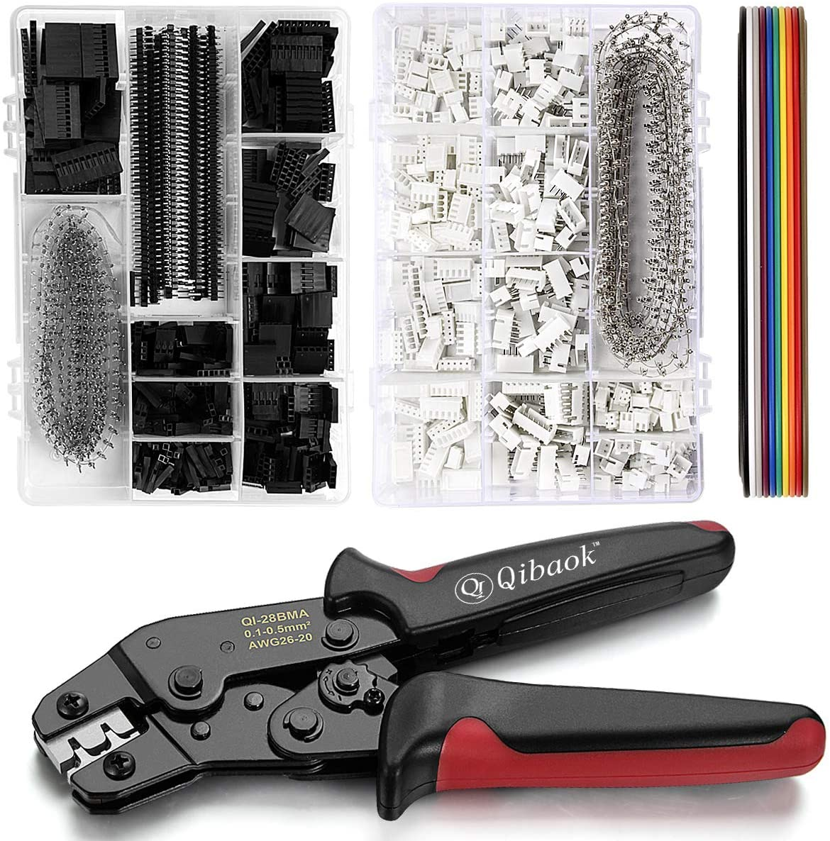
A while back, for my DIY 8 Bit Computer Project, I needed to make several Dupont connectors onto the end of some, yes...you guessed it, RAINBOW RIBBON CABLES 😁. I found a nice Dupont Starter Set With Crimper on Amazon, and it came in handy again for a clean solution to connecting the keyboard prototype to the TS-1000 PCB.
I desoldered the original keyboard connection headers from the PCB, and soldered in male pin headers. After splitting the ends of the ribbon cable into the two groups of rows and columns two inches, I proceeded to split the individual strands enough to crimp on the female Dupont sockets. The sockets have a tab that snaps into the plastic connector, locking them into place. Thirteen crimps and snaps later and I had connectivity between the TS-1000 and the prototype keyboard.
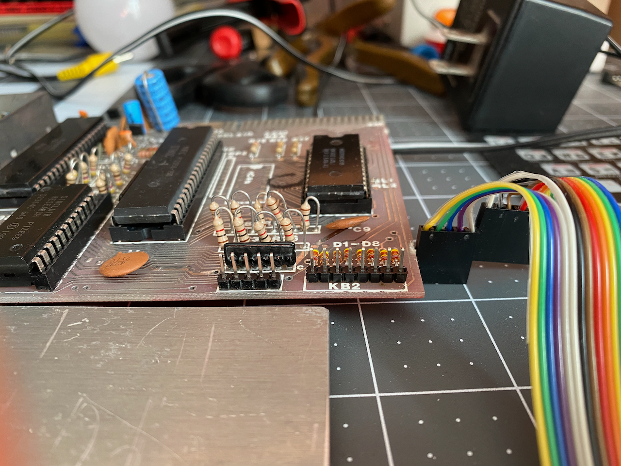
The feature image to this blog post was taken the first time I connected the newly connected keyboard to my TS-1000, but it wasn't plugged in yet. I connected power and my monitor to the composite video output jack of the modded RF modulator housing, and Voilà, It worked! My failure to get a keyboard to work when I was fourteen was now corrected, albeit forty years later, but better late than never. Not to sound overly dramatic, but sincerely, it felt like a weight being lifted from my shoulders. Funny how some things stick to our subconscious.
ZX81 Key Cap Labels
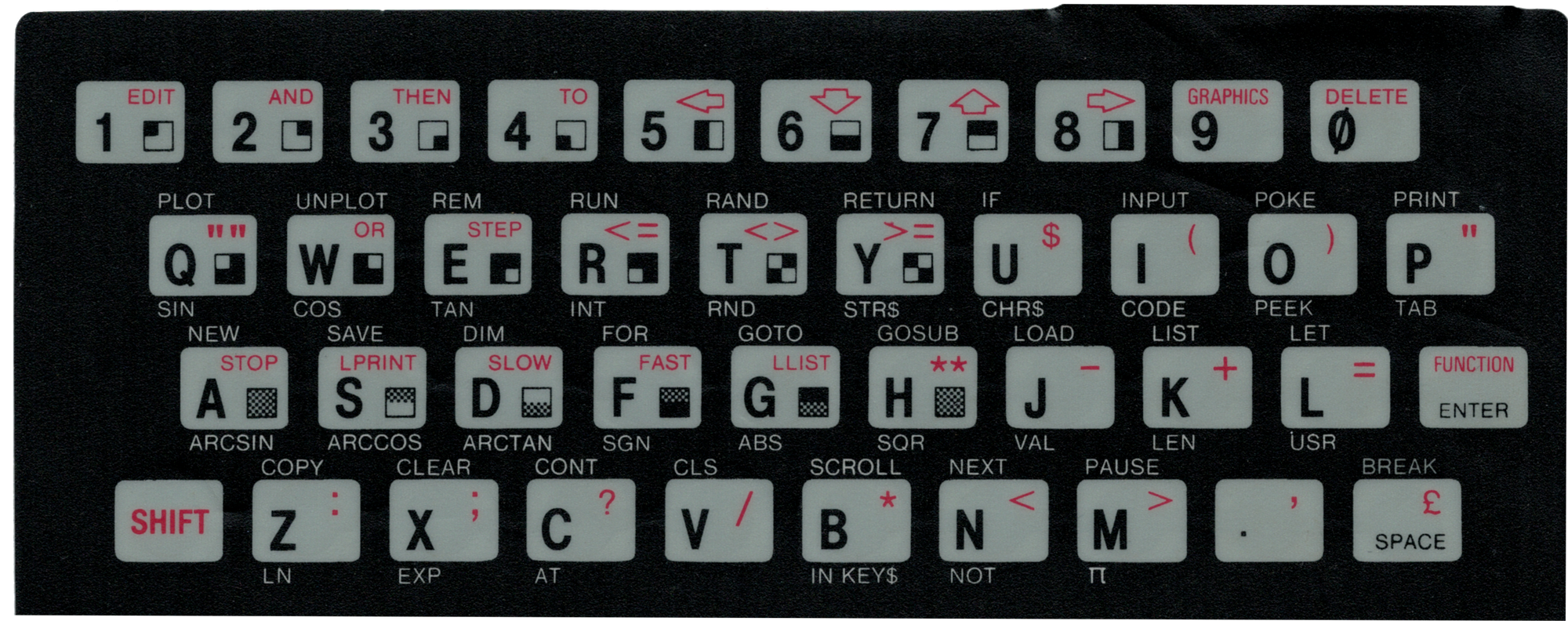
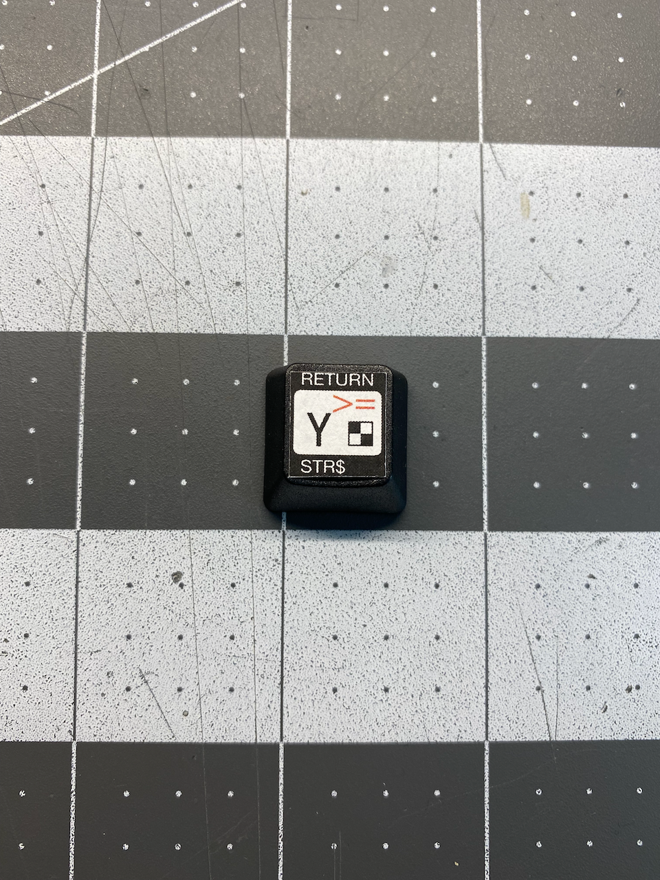
The labels on each key of the ZX81/TS-1000 have a lot going on! Like most keyboards, there is the main key character or modifier, such as an uppercase alphabetic character, a digit, or a function like "Shift" or "Enter". Since the ZX81 does not have lowercase letters in the system, the shifted keys are not the uppercase version of the alphabetic characters you would expect on other keyboards. Rather, the shifting of most keys results in certain symbols, system commands, or BASIC commands.
Many keys also have a graphical entity that can be invoked after switching to "Graphics Mode" on the keyboard ("Shift" & "9"). Outside of the keys there are "Keywords" (which are also system or BASIC commands) above some keys, and lastly "Functions" underneath a lot of the keys. So in the original keyboard membrane, these additional commands can be put above and below the actual keys, but with a mechanical keyboard all of that information needs to fit on the top face of the key cap. The key cap face dimensions of the key caps that I bought from Amazon are roughly 12.3mm wide x 14mm tall, which is not a lot of room to fit that much information.
On Top or on the Front Side?
The Functions that appear on the bottom of many of the keys could be applied to the front side of the key cap, providing more room on the key cap face, but that would require added complexity to the design of the decal file. Moving the Functions to the front side would also create extra work for applying additional decals to the key caps.
When thinking about the time to make a single file from which I could quickly and easily print out and cut key cap decals from, I realized that standardization would be my friend, so I figured a single key SVG template holding the geometry and font size/style/color information could easily be duplicated and then edited to make the entire keyboard matrix.
Inkscape To The Rescue
For anyone reading this post that hasn't already tried Inkscape, I highly recommend it. Inkscape is an Open Source and FREE alternative to other vector image editing software out there for purchase, a popular paid application is Adobe Illustrator (as of this writing, Adobe is offering a free trial). Inkscape works on Linux, Mac, & Windows, but as free software often goes, it lacks the polish and reliability of paid software in some areas. I'm not a professional graphics designer, so Inkscape more than meets my needs.
The choice for using Inkscape and vector images for the decal template was based on how vector images differ from "Raster" images. Image information in a vector image is saved in a way that allows vector images to be scaled from extremely small to extremely large without any loss of image quality or detail. Vector images store actual coordinates or relative distances between points, lines, and shapes in a virtual space rather than recording the color of individual points/dots/pixels that make up an image. When raster images are scaled up they become "Pixelated" like something from Minecraft (more on SVG in web development from MDN).
Since I want to end up with a template to represent the spacing of all the stuff on a standard key of the ZX81 keyboard, and I was already comfortable with using Inkscape, I went ahead and scanned my membrane keyboard into a PNG file and opened it in Inkscape as a guide for building my first key template.
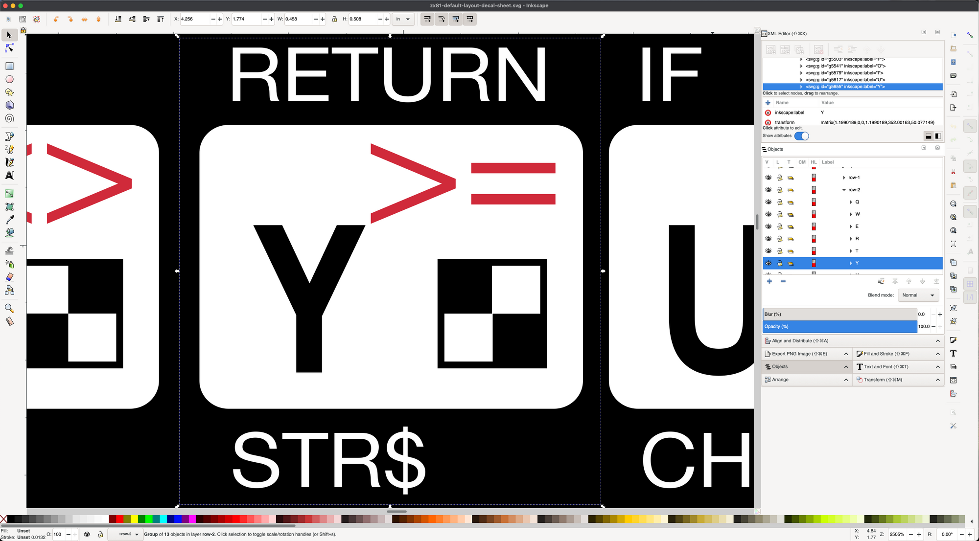
I somewhat arbitrarily selected the "Y" key as my starting point as it contained all elements that could possibly be present on any given key of the keyboard. With the scanned image of the keyboard inserted in the background of the new SVG file in Inkscape, I started adding shapes and text elements and positioned them so that they matched with the scanned key. I played with the fonts available to get a sans serif font (Helvetica Neue) that somewhat resembled the original font of the original keyboard. I also quickly decided on a higher contrast scheme for us older computer nerds 🤓, replacing the grey background for white. The white color choice in the file background (or transparent - no background color) also translates to no toner transfer during printing, and since I had selected waterslide decal paper with a white backing, it would be only the black and the red toner that should be transferred/printed.
The red chosen was just eyeballed to be similar, and somewhat more saturated for better visual contrast. Once the colors, fonts, and position of the shapes and text were to my liking, I printed the key out on plain paper using my laser printer to start playing with the scaling and find the best fit on one of the key caps. The print was also using the default resolution just for proof purposes.
Once I felt comfortable with the scale and layout of the "Y" key template, I started duplicating the "Y" key group of elements into a row of ten keys, and then I duplicated the row four times into a full layout of forty "Y" keys.
The next step was to go into each "Y" key of each row thirty nine times and edit the elements to be what they should actually be to be the correct key in that position. I put on my headphones, some 80's tunes and edited until I was done. When that step was completed, I had one complete keyboard layout that I could print.
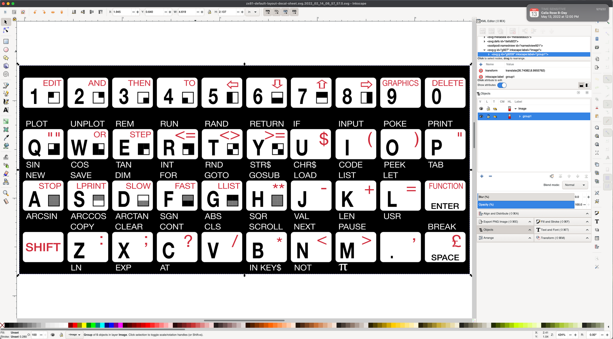
Seeing a complete keyboard on a sheet of U.S. Letter size paper seemed like an awful waste of waterslide decal paper when the time came to print a set of decals, but with Inkscape I could easily select the keyboard group of elements and duplicate it enough times to fill more of the page.
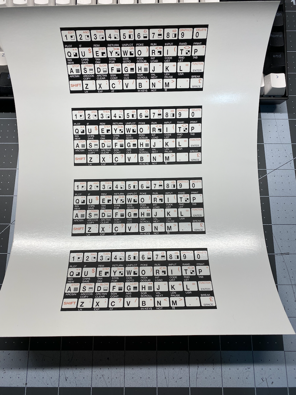
First Issue - Cutting the Decals
The first time I attempted to cut the decals from the waterslide decal paper, the edges of the black toner were cracking away into rough edges, exposing the white backing of the decal paper. Needless to say it really bummed me out! At one point during my research into how I could make my own decals, I saw something about sealing decals printed on inkjet printers with clear varnish to prevent bleeding while they are in water. I thought maybe the addition of the clear enamel might provide extra bonding and ductility to the toner on the decal paper, so I decided to try spray painting a few light coats of clear enamel (Rust-oleum Clear Satin) over the decals before cutting. It made a difference, but I was still experiencing issues on following print runs. On my next set of keys I may try a different brand or a gloss finish instead of satin.
Second Issue - Decals Peeling Off
About a day and a half after applying the decals to the key caps, the corners of most of them started lifting, and were easily peeled off with little to no effort. I was pretty certain before starting that the waterslide decal idea might only be viable as a prototype approach, but never imagined that the decals would be so problematic.
I built a lot of plastic models as a boy, and almost every model I ever built included waterslide decals. I do not recall ever having decals peel, and certainly not so soon. The key cap faces do have a slightly roughened surface when you look closely, so maybe it is that roughness that prevented the decals from adhering properly? Or maybe it was oils from my fingertips while typing on the keys before I applied the labels? Either way, I was determined to soldier on and find a solution.
After some researching and watching a few YouTube videos on waterslide decal application and solutions, I decided to try Testors Decal Set. My initial attempt was to apply it underneath and on top of the decals that were peeling off, but after the trial keys air dried, the decals were still lifting off of the key caps.
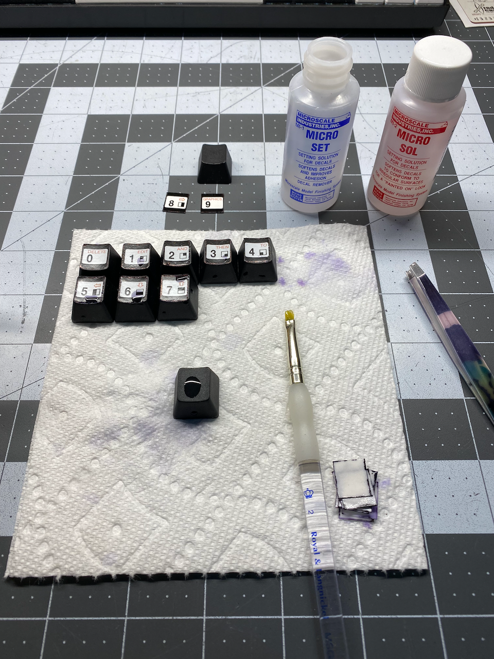
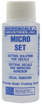
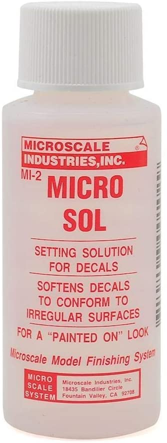
From all my previous research, I was aware of a two part system for treating/applying waterslide decals, made by Microscale Industries, Inc. (see links below) that did the trick. I think the combination of the two solutions made it possible for the decals to properly bond to the key caps, most notably the second step of softening the decals, which was lacking in the Testors decal solution.
Added Insurance
I waited several days to see if the decals were showing any signs at all of peeling up on any of the corners, and to my delight, none were. Even though this is only supposed to be a prototype, I could imagine that repeated key strokes could cause the decals to lift or eventually wear off of the key caps. All of the shear forces from my finger tips on every repeated key stroke would certainly become an issue, and after all the time and effort to get to this point, I was going to want something durable.
I already had a can of clear spray enamel in a satin finish, so why not put a few coats over the key caps to give the decals some added protection? I got a scrap piece of wood and bought some paper drinking straws from Michael's arts & crafts store. The straws were almost the perfect size, just a bit snug for the key cap I bought, but the paper straws stretch just enough if you're patient and don't force it.
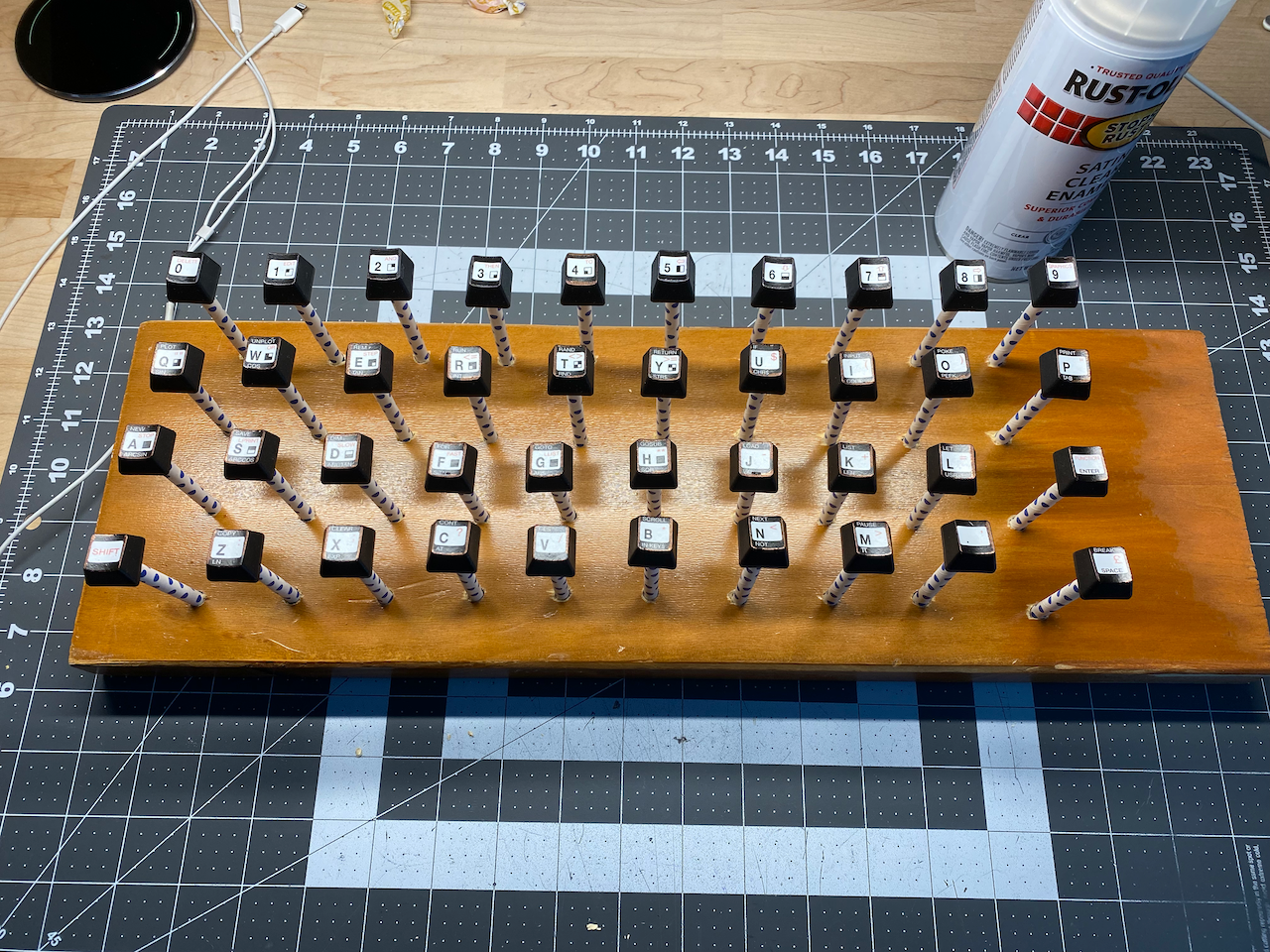
I sprayed several light coats of the clear satin enamel all around the faces and the four sides of all the key caps. One added benefit of adding the satin enamel was that the toner on the decals, the permanent marker I had to apply to the crackled edges of the black toner, and the key cap plastic all had different levels of black and also different finishes, but the clear satin coating made those differences much less apparent.
What's Next?
Using the keyboard is a real delight, the sound ("clickyness" is the proper technical term 🤓), the feel, and the look of the keys is truly a thing of joy, but now there is a new problem... having a better keyboard allows me to type faster than my poor Zeddy can keep up with.
I am already thinking about making a PCB instead of hand wiring the key switches, and also about adding a GAL/CPLD/microcontroller to the keyboard to allow for different keyboard layouts and things like "Shift Lock" or dedicated arrow keys. It would be great for users to be able to update firmware for custom keyboard mappings as well.
Another feature of adding a controller/logic to a PCB in the keyboard was brought up during the Timex/Sinclair Online User Group meeting on 4/4/22. A discussion started at timestamp: 01:35:00 about how nice it would be to add a keyboard buffer!
Alternative keyboards for the Sinclair computers start at timestamp: 00:54:00, and I mention my prototype keyboard at timestamp: 01:05:07, followed by more keyboard discussions.
For anyone interested, the Timex-Sinclair User Group meets on the first Monday and third Sunday of every month on Zoom. The YouTube channel is Timex Sinclair Fans, and the web site is Timex/Sinclair Computers. To get on the mailing list for the zoom meetings go to https://www.timexsinclair.com/about/community/. David also has a blog on the web site with some great content.
In closing, I hope that these posts save others time in making their own custom mechanical keyboards for their Zeddies, or offer some inspiration to make mechanical keyboards for other models of retro computers.
If you haven't already, please subscribe to my blog (It's free, and I don't share emails with anyone else) to get an email notification every time I post something new.
Source Files
The files used to make the mounting plate in part 1 of this series, and the decal file used in this post are available on Github.